Wiring Diagrams and Schematics:
Asymmetric DCC - My equivalent of the Lenz BM1 module.
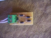
Schematic
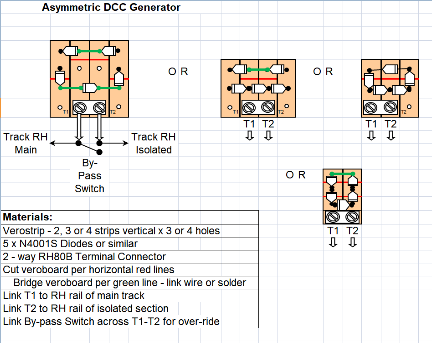
Apologies for the non-standard circuit symbols for th ediodes.
For more information about ADCC see Lenz/ADCC website.
Use of LEDs
LED indicators for points position using SPST switch such as Peco PL-13:
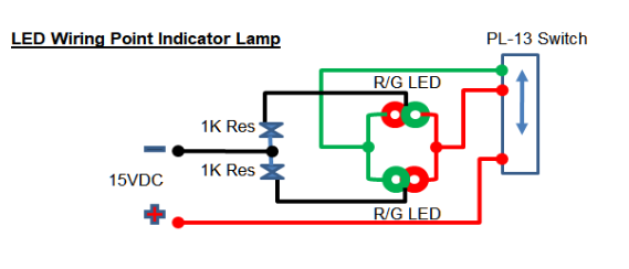
LED indicators for blind sidings without switches:

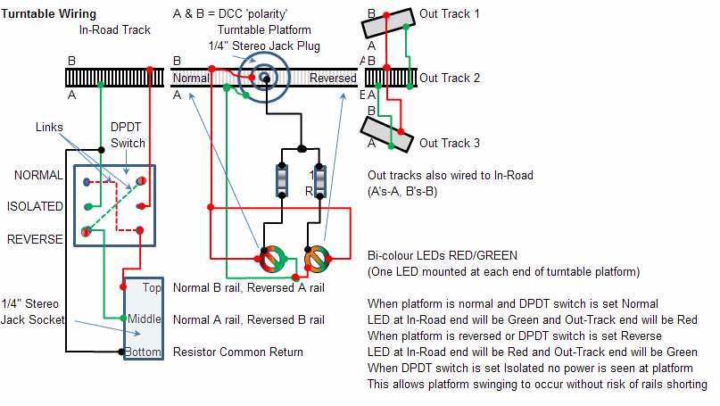
Wiring Turntables for DCC using a 1/4” Stereo Jack and Socket as the pivot and power feed:
Wiring points motors for dual DC and DCC operation:
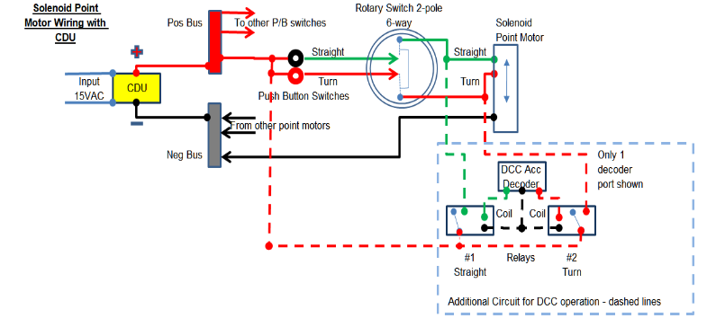
You can use any ‘analogue’ method of operating your points in lieu of my rotary switch/press-to-make switches - e.g. probe and stud, centre biased (ON)-OFF-(ON) switches, passing contact, etc.
All my system does is use the DCC signal to pulse into a relay coil long enough to simulate the analogue switching system, which fires the CDU into the appropriate side of the solenoids, ensuring reliable operation of your points, even if more than one solenoid motor is tied to a selection - e.g. a 2 points in a crossover loop to loop.
Note that my system fires the CDU output through the switches which could reduce their reliability.
To be continued…
ROB’S RAILS 
Wiring Diagrams and Projects
This page shows you wiring diagrams for some of the projects I have designed.
Please feel free to make use of them on the basic understanding that if you destroy any of your kit trying out these schemes then on your own head be it.
Please note that I cannot be held responsible for your actions, nor for any damage if the designs don’t work for you, but as far as I know the designs are safe and sound for amateur use.